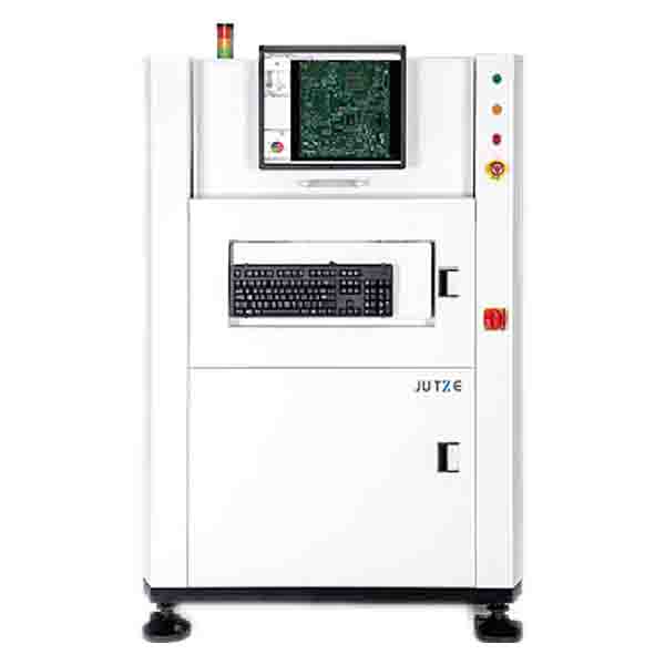
JHIMS | JUTZE AOI Machine PCB inspection system Video Tutorial

JUTZE AOI Machine PCB inspection system

Ⅰ、Operation manual introduction

    JUTZE AOI PCB inspection machine, inspection algorithm programming manual, click to download.


 Ⅱ、JHIMS | JUTZE AOI PCB Inspection Machine Video Tutorial - Part 1

Content description
The provides an installation, connection, startup, and safety inspection guide for the JUTZE AOI (Automated Optical Inspection) machine. Below are the key points:  
Summary
1. Receiving and Unboxing the Equipment  
- Upon receiving the AOI machine, do not rush to connect the power; first, check the machine’s condition.  
- During transportation, the XY moving axis of the machine is fixed to prevent the working head from moving randomly.  
2. Inspection and Connection  
- Clear any items and fixtures inside the machine before proceeding.  
- System Disk Backup: A black solid-state backup disk is provided. If the system fails, you can directly replace it.  
- The D drive also contains a system backup for double protection.  
- Connect to a 220V power supply and properly install the power cord, air pipe (0.45-0.5Mpa), and signal cables.  
- Network Connection: The AOI machine can be connected to a maintenance station computer or multiple machines through a switch and server for centralized control.  
3. AOI Machine Operation Modes  
Offline / Online Inspection:  
  - Online Mode: Inspection result data is transmitted to the computer for judgment.  
  - Signal Line Connection: Must be properly connected based on PCB flow direction (left to right or right to left).  
4. Pre-Startup Inspection  
- Check whether the XY axis and width adjustment inside the machine are secured.  
- Inspect the PCB conveying channels to ensure there are no obstructions and that the machine is clean.  
- Adjust the machine's leveling feet properly.  
- Ensure that the power cord, network cable, and air pipe are correctly connected.  
5. Machine Startup 
- Turn on the power only after all inspections are completed.  
- The machine is equipped with a wireless network card to connect to WiFi.  
- Select Software Language (English or Chinese, but both cannot run simultaneously).  
- Open the software and enter the AOI operation window, following the on-screen prompts.  
- Press the start button, and the X, Y servo motors will begin operation.  
- Manually move the XY axis to an appropriate position to avoid contact with the limit sensor.  
- Ensure no obstacles inside the machine, then press Start, and the machine will return to zero and enter standby mode.  
6. Remote Assistance  
- A remote assistance software is installed on the system desktop. If any issues arise, open the software and allow remote troubleshooting. 
 
Ⅲ、JHIMS | JUTZE AOI Automatic Optical Inspection Algorithm Tutorial - Part 2
Summary:
Introduces how to capture PCB (Printed Circuit Board) image of the operation process, mainly involved in PCB size measurement, channel width adjustment, image capture and save the key steps.
Specifically includes:
1. Measuring PCB dimensions: demonstrates how to measure the length and width of the PCB and emphasises the importance of accurate measurement.
2. Adjust PCB channel width: Adjust the channel width of the machine through the software menu to ensure that the PCB can be placed correctly.
3. Image Capture: Operate the AOI (Automatic Optical Inspection) equipment to capture PCB images, including how to load the board, adjust parameters and use shortcut key operations.
4. Image Storage: Instruction on how to save the PCB image in edit mode for subsequent writing of the inspection procedure.
5. Manual Adjustment of Channel Width: describes how to manually adjust the channel width without knowing the PCB size, including mechanical adjustment and safety operations.
6. Equipment reset and startup: describes how to restore the initial state of the equipment and load the PCB for inspection preparation.
7. Follow-up content preview: the end of the video mentioned that the next issue will introduce AOI programming and defect detection algorithms.
 

Ⅳ、JHIMS | JUTZE AOI Automatic Optical Inspection Algorithm Tutorial - Part 3

Summary:

This tutorial video explains AOI (Automated Optical Inspection) programming. The main contents are as follows:
1. Introduction
Explains the basic process of AOI programming and explains the goal of this step.
Emphasises the necessity of importing coordinate data for subsequent inspection.
2. Exporting Coordinates
Introduces two sources of coordinates: GERBER files and pick-and-place machines.
Points out that the coordinate accuracy of GERBER files is low, while the data exported by the pick-and-place machine is more accurate, and it is recommended to use the latter.
Detailed instructions on how to export coordinate files from the pick-and-place machine for use in the AOI process.
3. Processing the Coordinate File
Explains how to create an Excel file to store coordinate data.
Explains how to open the exported coordinate file and ensure that the data format is correct.
Instructs users on how to organize coordinate data to meet the requirements of subsequent import.
4. Importing and Using the Data
Explain how to open, check and import coordinate files in AOI software.
Explain how to view data after importing and ensure that the software can parse it correctly.
Emphasis on the need to check the integrity and accuracy of coordinate data to avoid affecting detection.
5. Final Steps and Conclusion
Summarize the key steps of importing coordinate data.
Remind users to check whether the data is complete to ensure that the subsequent AOI runs normally.
Summarize the role of this step in the entire AOI programming and prepare for subsequent operations.
Conclusion:
This video mainly explains how to correctly import the coordinate data of the placement machine and use it in the programming process of the AOI equipment. Emphasis:
1. The coordinate data of the placement machine is more accurate than the GERBER file.
2. The data needs to be processed in Excel before importing into the AOI software.
3. After importing, the data needs to be checked for integrity to ensure detection accuracy
 
Ⅴ、JHIMS | JUTZE AOI Automatic Optical Inspection Algorithm Tutorial - Part 4
Content summary:
This video introduces JUTZE AOI (Automatic Optical Inspection) programming. The main contents include the following parts:
1. Introduction to the operation interface
     The operation interface of AOI programming is explained. It is explained that the offline programming software and the online machine operation interface are exactly the same. The difference is that the software cannot control the actual operation.
2. Open the previously created program
     Use the sample program named "ABCD" to introduce how to open the program in design mode and view the PCB (printed circuit board) image.
     Explain that usually, the PCB image will not be displayed when the program is opened for the first time, and it needs to be imported manually.
3. Enter the edit mode for image import
     Explain how to import the PCB image in the edit mode and place it correctly in the operation interface.
4. The role and creation of mark points
     Mark points are used in AOI machines to accurately locate the position of the PCB board to ensure the accuracy of the inspection process. Explain how to create mark points on the imported PCB image and how to adjust its position and parameters for machine recognition.
5. Other related operations
     May also involve some detailed settings or optimization steps, but the specific content may require more detailed analysis.


Ⅴ、JHIMS | JUTZE AOI Automatic Optical Inspection Algorithm Tutorial - Part 5

The video explains the resistor programming in the JUTZE AOI system, which mainly includes the following steps:
1. Introduce the programming goal
Continue yesterday's programming task, today we focus on the programming of resistors.
Use a sample resistor for demonstration.
2. Enter the programming interface
Enter the programming interface by double-clicking.
Identify the resistor and select the appropriate component type (such as capacitor, transistor, etc.) in the interface.
3. Configure the resistor information
Copy the chip component's part number (Part Number) and paste it into the component library.
Create a new pad window to ensure that the soldering point is correctly defined.
4. Adjust parameters
Set the shape and size of the component to match the actual resistor.
Adjust the detection area and parameters to ensure detection accuracy.
5. Complete programming
Save the settings and test.
Ensure that the detection is accurate and avoid misjudgment or missed judgment.
In summary, this teaching video mainly guides users on how to correctly write the resistor detection program in the JUTZE AOI device, involving interface operation, parameter adjustment and component configuration.
 
Ⅴ、JHIMS | JUTZE AOI Automatic Optical Inspection Algorithm Tutorial - Part 6
This video mainly explains the detection and production process of resistors, including:
1. Review of the previous part
Introduced the basic principles of the resistor detection algorithm.
Explained the detection process of a specific resistor.
2. The main content of the current part
Focus on how to handle the detection of multiple resistors, not just the previous single resistor.
Discussed unfinished resistors and thought about how to quickly complete their algorithm programming.
Introduced methods to optimize the detection process and improve the efficiency of the automatic optical inspection (AOI) system.
3. Key issues
How to make the detection algorithm of resistors faster and more efficient?
How to complete the detection programming of all resistors?
How to optimize the identification and processing of resistors?
4. Conclusion
By improving the algorithm and optimizing the programming, the AOI system can detect resistors more accurately and efficiently.
This part provides key guidance for the integrity of resistor detection.


Ⅴ、JHIMS | JUTZE AOI Automatic Optical Inspection Algorithm Tutorial - Part 7

This video explains the specific steps of resistor programming, including:

1. Continue to use the last method to complete the production of resistor programming.
2. Select the resistor parts library of the same or similar size and copy the resistor name.
3. Update the parts library after ensuring the name is consistent.
4. Adjust the window size to match the resistor size and modify the parameters.
5. Set the search range and adjust the X and Y coordinate alignment to make the detection algorithm effective.
6. Optimize the programming process by modifying the algorithm, turning off the color, adjusting the window, etc.
The video mainly introduces how to use the same method for resistor programming and emphasizes the importance of parameter adjustment and name matching.


Ⅴ、JHIMS | JUTZE AOI Automatic Optical Inspection Algorithm Tutorial - Part 8

This video explains AOI (Automatic Optical Inspection) programming. It mainly involves the following content:
1. Open the inspection program: load the previous inspection program and wait for it to run.
2. Load the PCB board image: import the image of the PCB board and prepare for inspection.
3. Write a transistor inspection program:
    Select a transistor and copy the name to the parts library.
    Create a window to grab reference images for inspectors to compare.
    Create another window for subsequent algorithm positioning and select inspection defects (such as bad pads).
4. Select the inspection algorithm:
    Select the photo algorithm and adjust the light source to optimize the inspection effect.
    Set the inspection window to match the pad size.
In general, the subtitle content mainly introduces how to perform automatic inspection programming of transistors through AOI software, involving key steps such as image loading, window setting, light source adjustment and algorithm selection.


Ⅴ、JHIMS | JUTZE AOI Automatic Optical Inspection Algorithm Tutorial - Part 9

Summary of video content

Mainly introduces the inspection algorithm of SOP chips, focusing on the detection of IC pins. The following are the main contents:
1. Window adjustment and component matching
◆ Adjust the window size to make it the same as the component size.
◆ Select the SOP type and copy the IC name to the parts library.
2. IC pin detection algorithm
◆ Introduce the Leadbox detection algorithm.
◆ Adjust the detection window to make it consistent with the width of the IC pin and adjust the height appropriately.
◆ Turn off the color display to observe the detection area more clearly.
◆ Make the window cover the IC pin and part of the pad area to ensure the integrity of the detection.
3. Window debugging and optimization
◆ Select the body of the IC pin and adjust the detection window size to match the pin.
◆ Move the window step by step to ensure that the detection size is appropriate.
Summary: This tutorial mainly explains how to make the detection algorithm of the IC pin part, and does not involve other algorithms such as loss detection, offset detection, and angle detection. The entire process includes window adjustment, area positioning, algorithm selection and window debugging to ensure the accuracy of detection.


Ⅴ、JHIMS | JUTZE AOI Automatic Optical Inspection Algorithm Tutorial - Part 10

This video content involves the identification of poor chip component assembly and precautions for color debugging.
Content Summary
This video introduces how to identify poor chip component assembly and precautions for color debugging. The main contents include:
1. Determination of poor product assembly
◆ Missing or missing components
◆ Component offset (chip position downshift)
◆ Wrong assembly direction (such as resistor or chip flip installation)
2. Identification of poor welding
◆ Cold welding phenomenon, the color is blue-white or red
◆ Normal welding color should be dark blue or blue-black
◆ Parts with abnormal color usually have defects
3. Precautions for color debugging
◆ When debugging color and checking welding quality, avoid misjudgment of pink. Components with abnormal color may have quality problems


Service Hotline:

+86 18975335491

online service
JING HE

Website QR Code

Shenzhen Jinghe Technology Co., Ltd. © 【Sitemap】 
Powered by MetInfo 5.2.7 © 2008-2025 MetInfo Inc.